Introducing the ET-28
Electrical testing is a category of non-destructive testing (NDT) that employs instruments to measure electrical field parameters in interaction with a test object (TO). These methods have gained prominence for their effectiveness in defect detection, thickness measurement, and structural analysis.
Key applications of electrical NDT methods include:
- Identifying delaminations in sheet metals and casting defects.
- Assessing soldered joint quality.
- Detecting defective weld seams.
- Identifying delaminations in bimetallic plates.
- Measuring cracks in metallic components.
- Sorting or identifying metallic objects by conductivity.
Fundamentals of the electro-potential method
The electro-potential method (EPM) is the most widely used electrical NDT technique. It involves measuring the potential distribution on the surface of a TO to detect surface defects.

Figure 1: Schematic of electrode placement for defect depth measurement.
From an external source, electric current (AC or DC) is supplied to the examined area of the test object (TO). The current density is distributed along the current flow lines (Figures 2 and 3) between two current-carrying (current) electrodes, which are positioned at a certain distance from each other. As the current passes through the conductive TO, it creates potential drops across each area of its surface. The potential difference (U) in the inspected area of the TO surface is measured using measuring (receiving) electrodes placed at a fixed distance from each other.
The obtained value of U is used to evaluate the depth of surface defects as well as their dimensional parameters.
A surface defect, such as a crack, introduces an additional obstacle to current flow through the TO. In Figure 2, the arrangement of lines of equal current density—current density isolines—and lines of equal electrical potential—equipotential lines—is schematically shown for a defect-free area under DC current conditions. These lines are orthogonal to each other.

Figure 2: Diagram of current field line distribution and equipotential lines in a defect-free test object.
A comparison of the arrangement of lines in the absence of a defect (Figure 2) and in the presence of a surface defect, such as a crack (Figure 3), shows that a defect in the continuous conductive medium, oriented across the current density isolines, distorts both the isolines and the equipotential lines. This distortion leads to a change in the value of U between fixed points on the surface (measured by the receiving electrodes). This indicates the fundamental feasibility of conducting defect detection in conductive materials using the electro-potential method.
Figure 3: Diagram of the distribution of current field lines and equipotential lines in the test object (TO) in the presence of a defect
It is important to note that the current density in the area measured by the receiving electrodes depends on the following factors:
- The distance between the current electrodes.
- The distance between the current and receiving electrodes.
- The ratio of crack depth to the distance between the current electrodes.
- The electromagnetic properties of the metal (electrical conductivity and magnetic permeability).
- The thickness of the object under inspection.
In addition to measuring the potential difference UD between the receiving electrodes in the area with a crack, the potential difference U₀ is also measured in a deliberately defect-free area of the surface (Figure 4). The quality of the inspected area is assessed based on the value of the relative potential difference U', calculated using the following formula:
U'=(UD-U₀)/U₀

Figure 4: U₀ - the potential difference value between receiving electrodes in a defect-free area, UD - the potential difference value between receiving electrodes in a defective area, h - defect depth.
The depth of the defect h is determined by the ratio UD / U₀. This approach compensates for the influence of the material's specific electrical conductivity on the inspection results. Consequently, the value of UD / U₀ primarily depends only on the defect depth h and the relative positioning of the current and potential electrodes.
To ensure that the ratio UD / U₀=U′ is independent of the electro-physical properties of the inspected area when using direct current, it is sufficient for the specific electrical conductivities of the defective and defect-free areas to match. It is worth noting that the dependence UD / UD(h) is consistent across all nonmagnetic metals that are homogeneous in terms of specific electrical conductivity.
Typically, current and receiving electrodes are integrated into sensors, which are connected to the electronic unit of the device via cables. The electrodes are designed with sharp tips for secure placement on small areas and are spring-loaded to apply increased pressure in the contact zone. This design ensures not only better contact with the surface but also enables measurements on uneven surfaces.
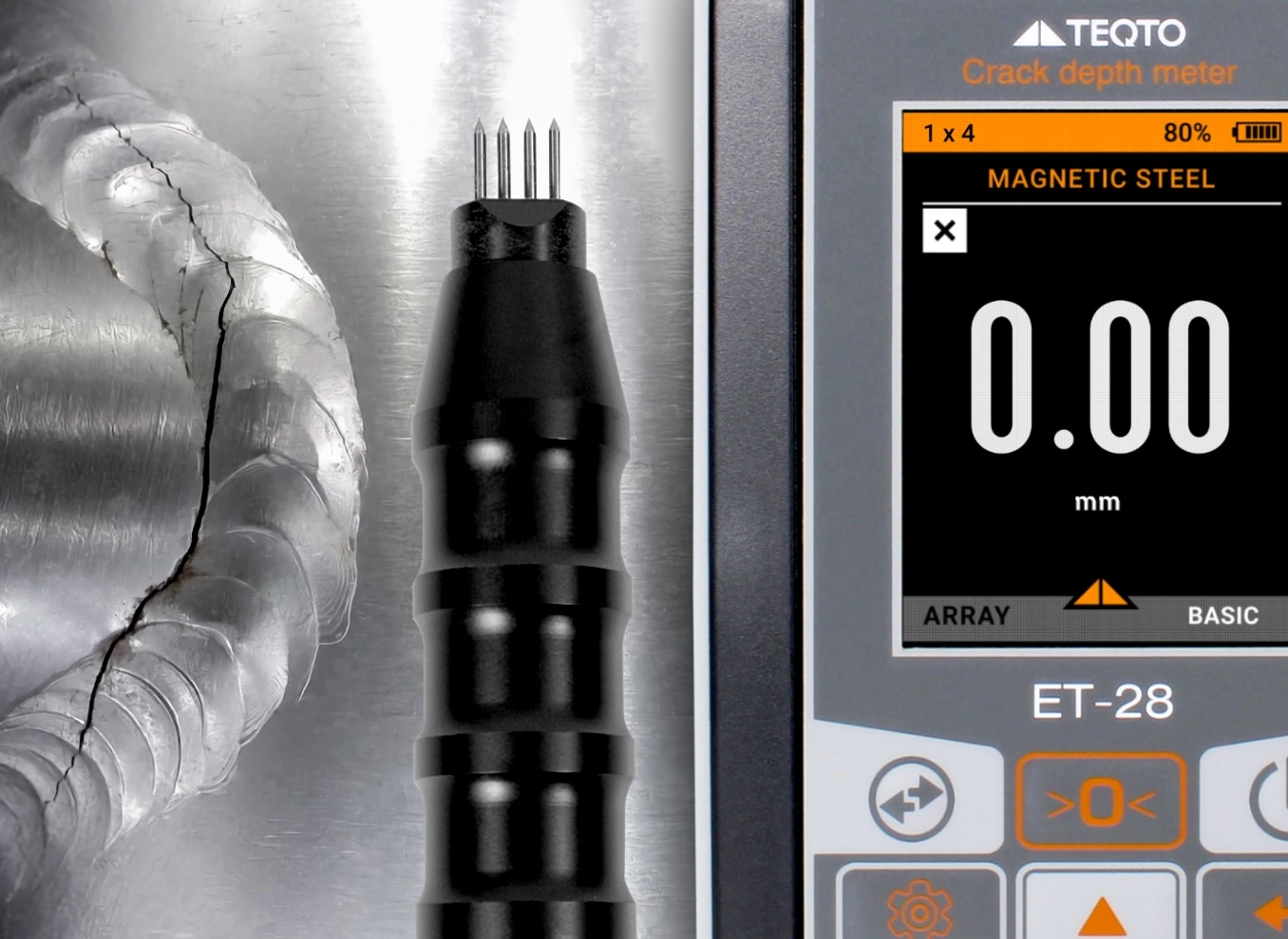
The most suitable material for manufacturing electrodes is hardened steel, which provides high wear resistance necessary for maintaining sharp tips over extended periods. Two main types of probes are commonly produced: four-electrode and three-electrode probes (Figure 5).
The four-electrode probe includes two current and two potential electrodes. These probes are designed with varying distances between the current electrodes, depending on the required measurement range.
Figure 5 illustrates various designs of four-electrode sensors for the ET-28 Crack depth meter:
- "1x4" probe: Electrodes are arranged in a single row and designed for measuring crack depths from 0.5 to 30 mm.
- "2x2" probe: Electrodes are arranged in two rows, suitable for measuring crack depths from 0.5 to 20 mm. This probe is ideal for use in hard-to-reach areas and on surfaces with closely spaced cracks.
It is important to note that the electro-potential method implemented in the ET-28 Crack depth meter allows for assessing crack depths of up to 100 mm. However, the calculated error value remains accurate only within the specified measurement range for each probe type.

Figure 5: Examples of probe configurations for TEQTO’s ET-28 Crack depth meter.
The three-electrode probe includes two potential electrodes spaced 2–5 mm apart and one current electrode. A second current electrode is designed as an external component equipped with a magnet for quick attachment to the desired point on the surface of the test object (TO). This design allows the current electrode to be positioned at a significant distance from the potential electrodes, ensuring the condition that "the crack depth must be less than the distance between the current electrodes" is met. This significantly reduces the non-linearity of the device’s readings when measuring cracks of varying depths.
Figure 5 shows the "3+1" probe with an external current electrode, which is used for measuring crack depths from 0.5 mm to 100 mm. This configuration is also convenient for use in hard-to-reach areas.
During probe manufacturing, special attention is paid to setting the distance between the measuring electrodes, as this directly affects the measurement accuracy.

Figure 6: ET-28 Crack depth meter and probes.
Limiting factors
- The reliability of crack depth assessment largely depends on the homogeneity and isotropy of the electrophysical properties of the test object’s material, primarily its specific electrical resistivity. This factor determines the maximum permissible accuracy for measuring the dimensional parameters of the test object.
- When measuring the depth of surface defects, the electro-potential method is effective only if the defect has significant linear extension, as is typical for cracks. The defect's length must be at least three times its depth. Consequently, while the electro-potential method is highly effective for evaluating crack depth, it may be less suitable for determining the geometric parameters of other defects, such as cavities, pits, volumetric inclusions, or pores.
Advanced solution by TEQTO
TEQTO produces a high-precision portable device for measuring crack depth—the ET-28 Crack depth meter, capable of measuring cracks up to 100 mm deep. Complemented by a range of probes and reference samples simulating cracks of various depths, it is an indispensable solution for industries requiring accurate, non-destructive defect analysis.

For unique requirements, TEQTO also offers custom-designed measuring instruments tailored to meet specific technical needs.
For custom inspection tools tailored to your needs, contact our team here.